Here We will discuss about dimmer circuit using TRIAC. Basics of TRIAC is not covered in detail, you can refer it on google.


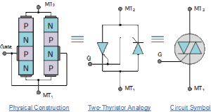
Diagram 1 above shows basic construction and symbol of TRIAC.
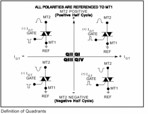
Diagram 2 shows Working Quadrants of TRIAC. Safe quadrants of working are Q-1, Q-2, Q-3 and we should avoid Q-4 as Gate current required to trigger TRIAC is much higher compared to other three quadrants. di/dt also reduces thus TRIAC may damage early.
Circuit shown below is Dimer using TRIAC:
 In this circuit, firing angle of TRIAC is adjusted by R-C time constant. here we have connected GATE terminal to MT2 so TRIAC works in 1st and 2nd Quadrant thus avoid 4th quadrant of operation.
In +ve half cycle capacitor C1 charge through R1 and R2 (upper plate +ve). when capacitor charges full and reaches Vbo of Diac D2, Diac starts conducting giving +ve supply to the TRIAC. TRIAC starts conducting and capacitor discharges. as soon as supply voltage reaches zero TRIAC stop conducting. In -ve half cycle capacitor charges with upper plate -ve and gives -ve supply to TRIAC gate through DIAC and cycle repeats.
When load is Inductive it supplies back energy stored in the coil into supply rail. this scenario can backup C1 which then evolves into not able to charge correctly. C2 assist C1 to keep up it’s cycle by offering bursts of small voltage even though C1 has totally discharged. thus keep the proper switching rate of triac.
By Varying the POT we can vary firing angle of triac thus controlling the Voltage output.


